


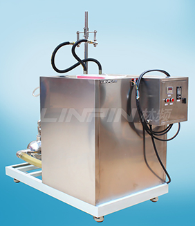
Climatic chambers for test standard SAE J575
An assembly (divisible or indivisible) which contains a bulb or other light source and generally an optical system such as a lens or a reflector, or both, and which provides a lighting function. Lighting device samples submitted for test shall be representative of the device as regularly manufactured and marketed, unless otherwise identified. The standard need a lot of climatic chambers, such as temperature test chamber, water-proof test chamber, salt spray test chamber and so on.
Each sample shall be securely mounted on a test fixture in its designed operating position and shall include all accessory equipment necessary to operate the device in its normal manner. An indivisible assembly which contains a source of light and which is normally used in a lamp.
Unless otherwise specified, bulbs used in the tests shall be supplied by the test facility and shall be representative of bulbs in regular production. Where special bulbs are specified, they shall be submitted with the sample devices and the same or similar bulbs shall be used in the tests. Lighting devices designed for use in 6V, 12V or 24V systems shall be tested with 12V system bulbs.
A device specifically designed to support the lighting device in its designed operating position during laboratory testing. This fixture, when used for the vibration test, shall not have a resonant frequency in the 10 to 250Hz range.
The following sections describe individuals tests which do not need to be performed in any particular sequence. The completion of the tests may be expedited by performing the tests simultaneously on separately mounted samples. However, it is recommended that the design of each device be evaluated to determine if vibration or warpage tests might affect the results of other tests, in which case the vibration and/or warpage tests should be performed first.
Thermal cycle test
This test applies to lamps that have a plastic lens, a plastic reflector, or both
The lamp shall be seasoned and photometered to the test points as per applicable standard before and after the thermal cycle test. The lamp shall be rigidly mounted in a test fixture in designed operating condition and designed mounting position.
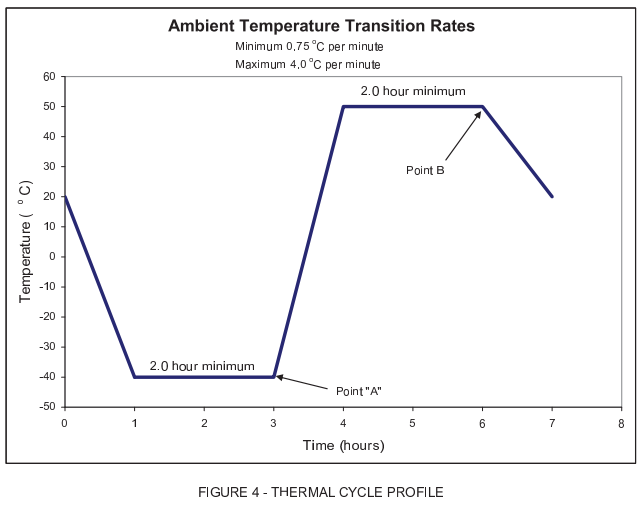
The lamp shall be exposed to the thermal cycle profile shown in Figure 4. The minimum temperature is -40℃ and the maximum temperature is 50℃. Separate or single test chambers may be used to generate the temperature environment described by the thermal cycle.
The lamp shall be energized at design voltage ±20mV, in its highest wattage mode commencing at point “A” of Figure 4 and de-energized at point “B” of each cycle. The test period shall be 10 cycles with 4.75 to 8h per cycle.
Internal heat test
The lamp shall be seasoned and photometered to the test points as applicable before and after the internal heat test. The lamp shall be rigidly mounted in a test fixture in designed operating condition and designed mounting position. A dirt mixture, consisting of Portland cement, distilled or deionized water, and a small amount of surfactant shall be uniformly applied on the face of the lens and allowed to dry until the light intensity at the maximum intensity location in the beam pattern is reduced to 25%±2% of the original value for the highest wattage function of the lamp. The mixture may be uniformly applied by spraying or brushing.
The lamp assembly shall be energized in its highest wattage continuous operation mode and placed in a chamber at 35℃±3℃ in still air. The test duration shall be 1h.
The test voltage for the lamp shall be design voltage ±0.1V. After the internal heat test, the lens face shall be wiped clean.
Solar irradiation
Lamps should be mounted in vehicle orientation, simulating vehicle solar exposure. Solar irradiation is provided directly above the lamp, at 90 degrees, solar intensity of 1047 to 1120 W/m² with spectrum similar to the solar spectrum per DIN 75-220 or MIL-STD-810F. Apply solar irradiation for 60min, with lamp off, to heat lamp with a ambient temperature of 45 to 50℃ and wind speed of less than 0.5m/s.
Power lamp on, with solar irradiation ON and maintaining 45 to 50℃ ambient with wind speed less than 0.5m/s, at design voltage and the duty cycle conditions listed below. Do not combine functions during testing, test only one function at a time. Suggested testing cycles are: Stop function-continuous on for 30min, Tum function (hazard mode) -flashing for 60min per Table 1, Headlamp function (low beam and sidemarker) one for 60min continuous, DRL-60min constant on.
Repeat above steps but with the solar angle at 50 degrees from horizontal and incident normal to the function being tested, with solar intensity of 800 to 860 W/m2 .
Water intrusion (moisture) test
This test evaluates the ability of the sample device to resist moisture intrusion from a water spray and determines the drainage capability of those devices with drain holes or other exposed openings in the device. This test is not intended to provide a complete test on the device seal (see Dust exposure test). A sample device as mounted on the test fixture shall be tested according to either the water spray test type A, type B or water submersion test as applicable.
The purpose of the water submersion test is to reduce the test time for sealed lighting devices. Devices which comply with the water submersion test or water spray test type A or type B are considered to have complied with all requirements of the water intrusion (moisture) test. Compliance reporting should include which water intrusion test was chosen.
1. Water spray test-type A
The following equipment shall be used.
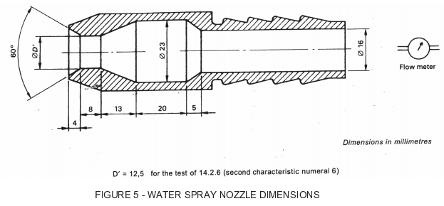
A water spray cabinet shall be equipped with a nozzle which provides a solid cone water spray of sufficient angle to completely cover the sample device. The centerline of the nozzle shall be directly download at an angle of 45±5 degrees to the vertical axis of a rotating test platform.
Having a minimum diameter of 140mm and rotating about a vertical axis in the center of the cabinet. The precipitation rate of the water spray at the device shall be 2.5+1.6/-0mm/min as measured with a vertical cylindrical collector centered on the vertical axis of the rotating test platform. The height of the collector shall be 100mm and the inside diameter shall be a minimum 140mm.
The mounted sample device shall be subjected to a water spray as follows:
All drain holes and other openings shall remain open. Devices having a portion completely protected in service (e.g., trunk mounted lamps) shall have that part of the device covered to prevent moisture entry during the test. Drain wicks, when used, shall be tested in the device.
The device shall be rotated about its vertical axis at a rate of 4.0±0.5rpm. The water spray test shall continue for 12h. The rotation and the water spray shall be turned off and the device allowed to drain for 1h with the cabinet door closed.
Please visit www.lenpure.com


