


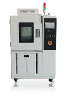
Climate Chambers for IEC-60749-25 : Temperature Cycling
About Climate Chambers manufacturer Shanghai Lenpure
Lenpure is a brand owned by Shanghai Linpin Group.
Lenpure is a leading manufacturer of climatic chambers in China.
Lenpure manufactures a wide range of test chambers including but not limited as below:
1. Temperature and/or humidity environmental test chambers
2. Weather aging environmental test chambers
(Xenon, UV, Ozone, Sulfur dioxide environmental test chambers)
3. IP level environmental test chambers
(IPX1-X6 rainfall environmental test chambers, IP5X-6X dust/sand environmental test chambers)
4. Walk-in environmental test chambers
R&D Team
Lenpure cooperates with Shanghai Jiao-Tong University as a R&D certer.
Lenpure has dozens of preeminent specialists in the industry.
Lenpure provides design, manufacture, QC, installation & training service.
Lenpure has rich experience in making various complex projects.
Our Partners
Lenpure gives first priority to providing satisfactory products and service.
Lenpure has established stable cooperation with lots of world-top-500 enterprises.
Lenpure opens its door for all friends from home and abroad.
This part of IEC 60749 specifies a test method for determining the resistance to mechanical stress caused by switching between high and low temperatures for semiconductor devices and other components and / or printed circuit boards. These mechanical stresses can cause permanent changes arising from electrical and / or physical characteristics.
This test method generally complies with IEC 60068-2-14; however, due to the particular requirements of semiconductor devices, the clauses of this standard are applicable. This test method is applicable to the one, two and three chamber thermal cycling method and is valid for testing both components and solder joints.
In the single-chamber change method, the standard is introduced into a stationary test chamber and then both heated and cooled by heated air, ambient air or cooled air is introduced (injected) in the chamber.
In the two-chamber changing method, the total test load is mounted on a movable carriage, which is moved back and forth between the stationary chambers. The chambers are kept at fixed temperature values. In the three-chamber changeover method, the total test load is moved back and forth between the three chambers.
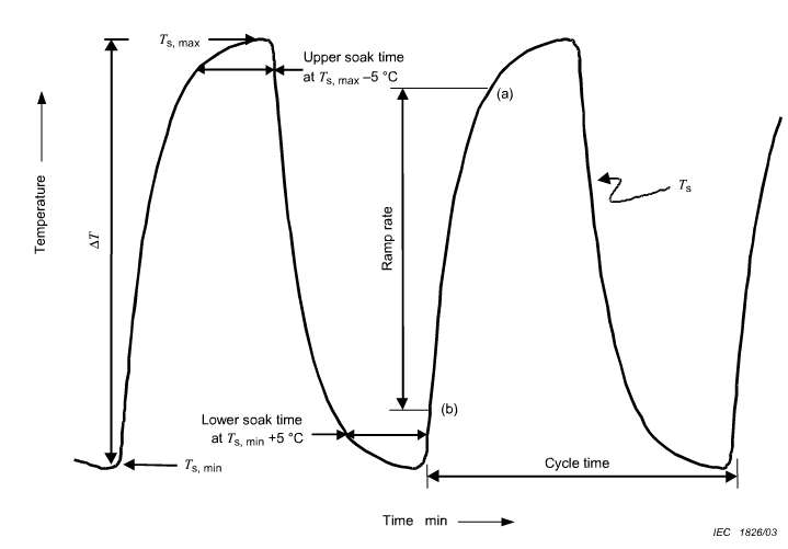
5.4 Upper and lower soak times
Upper and lower soak times vary by the soak mode selected; see Table 2. During this soak time, the specimen shall reach the required Ts max and Ts.min
5.5 Upper and lower soak temperatures
Upper and lower soak temperatures vary with the test condition selected; see Table 1.
5.6 Soak modes
Soak modes are listed in Table 2. Soak modes with longer soak times than those shown in Table 2 are not compatible with standard cycle rates and should be selected only as required for a specific failure mechanism.
5.6.1 Component soak mode
In component temperature cycling, soak mode 1 is typically used.
5.6.2 Interconnect soak mode
Soak modes 2, 3 and 4 are generally used for solder fatigue and creep testing associated with interconnections such as flip chip or ball grid array solder joints.
5.7 Cycle time
Cycle times vary with the soak mode selected. Table 3 lists typical cycle rates for components versus test condition and soak mode. For solder interconnections, cycle times less than30 min are not recommended.

5.8 Ramp rate
5.8.1 Component ramp rate
Ramp rate is not critical for most component testing.
5.8.2 Interconnect ramp rate
When testing interconnections for solder joint fatigue, it is important to avoid transient thermal gradients in the samples on test. Samples with large thermal mass and low heat transfer efficiency require ramp rates slow enough to compensate for the thermal mass.
The temperature of the sample should be within a few degrees of the ambient temperature during the temperature ramps. Typical ramp rate for this situation is 15 C/min or less for any portion of the cycle, with a preferred rate of 10 C to 14 C/min. For samples of large thermal mass, use of a single zone chamber may be required to achieve the best ramp rate.
For samples without a thermal mass constraint, the ramp rate can be faster and dual chambers can be used. Typical test requirements for solder interconnection are listed in Table 4. The combination of ramp rate and soak time are important when testing solder interconnections.
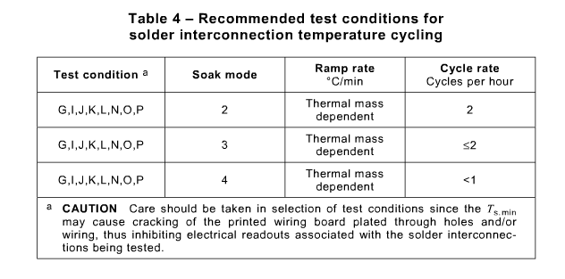
5.9 Load transfer time
For dual and triple chambers, it is recommended that the load transfer time shall be less than 1 min, in order to maintain a uniform temperature profile across the load. For single chamber equipment, the time to change the air from one temperature extreme to the other should be less than 5 min. This includes the introduction of ambient air if used.
5.10 Recovery
a)At the end of the conditioning period, the specimen shall be subjected to standard atmospheric conditions for recovery for a period adequate for the attainment of temperature stability.
b)The relevant specification may call for a specific recovery period for a given type of specimen.t
5.11 Final measurements
The specimen shall be visually inspected and electrically and mechanically checked, as required by the relevant specification.
5.12 Failure criteria
Failure criteria shall include. but not be limited to. hermeticity for hermetic devices, parametric limits, functional limits, mechanical damage (including solder joint integrity) and warpage.
Parametric and functional limits shall be defined by the relevant specification. Mechanical damage shall not include damage induced by fixturing or handling or the damage that is not critical to the package performance in the specific application.
6 Summary
The following details shall be specified in the relevant specification:
a) Special mounting, if applicable.
b) )Temperature extremes: see Table 1, soak time: see Table 2, sample cooling and heating amp rate (see 5.9) and number of cycles, or specific component requirements.
c) Interim measurement intervals, when required.
d) Special acceptance criteria for examinations, seal tests (for hermetic packages), internal bond integrity tests and electrical tests if other than those specified in the device specification.
e) For qualification testing, sample size and quality level.
f) Temperature extremes other than in Table 1. Specify the number of cycles, temperature extremes, soak time, cycles per hour, tolerance on temperature extremes (if different from Table 1).

If you are still interested in any kind of environmental test chambers, and I'm pleased provide some of our details and project to you. That's more, at present we have more attractive price for you. Welcome for inquiry any time, I will reply asap!
If you want to know more information about climate chambers or our company, please feel free to contact sales@lenpure.com or visit http://www.lenpure.com/ .


